
OEM Thoracic Aortic Stent Graft System Manufacturing: What Device Developers Need to Know
2026-10-12
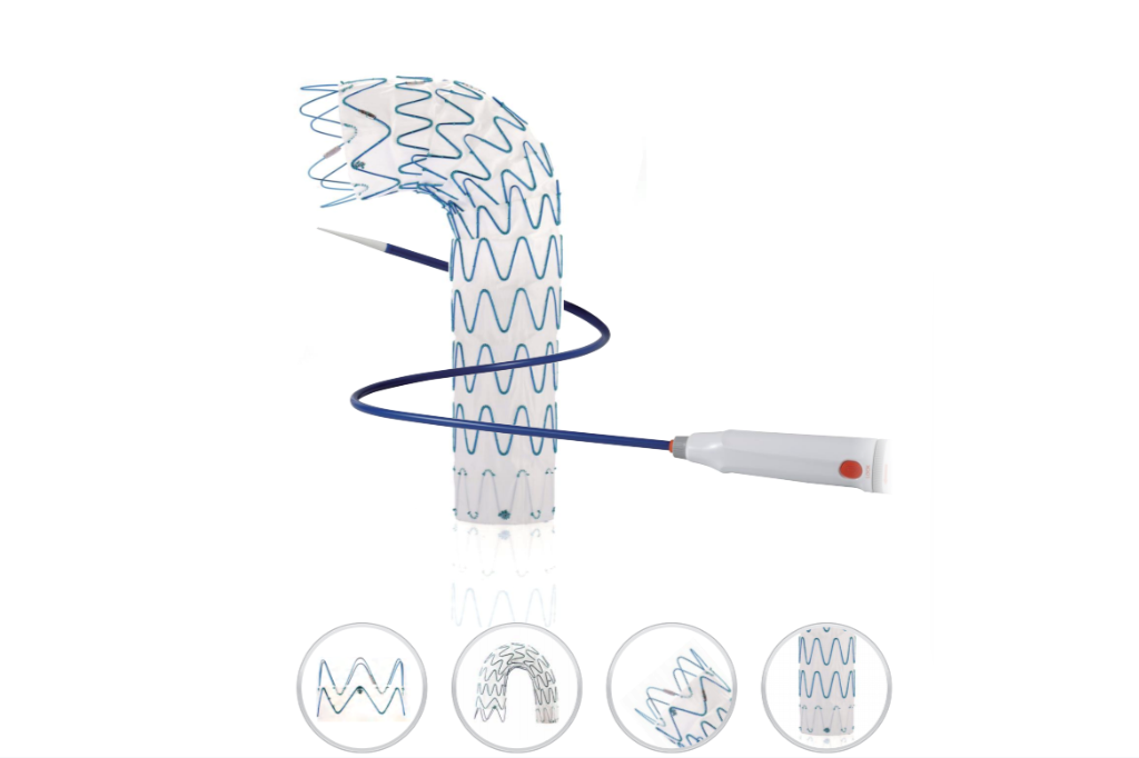
OEM manufacturing for thoracic aortic stent graft systems isn't just about scaling production—it's about controlling every variable that can compromise a device inside the human aorta. One wrong weld or an unverified lot of graft material can turn a breakthrough into a recall. At INT, we work with device developers to prevent exactly that. This article walks through the manufacturing decisions that separate successful programs from stalled ones.
Why Graft Porosity and Stent Ring Geometry Rarely Align on the First Try
The assumption that a designed pore size will survive the trip from CAD model to crimped device ignores how much fabric moves during assembly. A woven or knitted graft is not a rigid lattice; once sutured to a laser-cut stent ring, the peaks of each ring tend to stretch the fabric while the valleys let it bunch. That alone can shift local porosity by twenty to thirty percent, turning a nominal 100-micron window into a patchwork of wide and tight regions before any blood ever flows through.
Ring geometry adds a second layer of mismatch because most stent designs treat the graft as a passive sleeve. In practice, the crown angles and strut spacing dictate where the fabric can fold or bridge. A ring with sharp apices creates high contact pressure at discrete points, compressing yarns and effectively sealing pores there, while mid-strut zones stay relatively open. Even small changes in crown radius or strut width ripple through the textile, so the pore distribution ends up tracking the metal skeleton rather than the intended flow surface.
The first attempt rarely aligns because fabric behavior is nonlinear and anisotropic, yet early prototypes are usually evaluated against uniform porosity targets. Crimping to a low delivery profile further distorts the weave, and if the device is then balloon-expanded or self-expands in a mock vessel, the recoverable strain in the yarns does not match the plastic deformation of the ring. Getting the two to align takes iterative adjustment of stitch pattern, ring height-to-wavelength ratio, and crimp sequence—there is no shortcut that survives first contact with a real graft.
Early Supplier Talks That Prevent OEM Timeline Slips Down the Line
Waiting until the design freeze to bring suppliers into the room is a reliable way to watch your launch date drift. Early conversations—before drawings are locked and tolerances are set—let manufacturing partners flag tooling lead times, material availability issues, and process risks that the design team hasn't considered yet. That single change can pull weeks out of a schedule that would otherwise get eaten by late redesigns.
The real value shows up in the details. A supplier who sees a draft BOM can point out that a specified resin has a 14-week lead time, or that a stamped bracket needs a secondary operation to hold flatness. Catch those items during the prototype stage and they become line items on a risk register. Miss them until the production tooling order goes out, and the whole program pays for it in overtime, air freight, and missed gate reviews.
It doesn't require opening the books or handing over sensitive IP. A structured early dialogue—weekly technical syncs, shared CAD snapshots, and honest capacity checks—gives OEMs the visibility to adjust the plan before the critical path hardens. Suppliers who are treated as partners in the schedule, rather than order takers at the end of it, tend to solve problems earlier. That's what keeps the timeline from slipping when the pressure is highest.
Cleanroom Assembly Checks Most Teams Only Think About After Failure
During routine assembly, it's easy to skip the wipe-down of stainless steel fixtures because they 'look fine.' But after a batch fails for fiber contamination, suddenly everyone notices the crevice where residue hides. The check that gets added to the post-mortem list? A UV light inspection of all tooling joints—something that takes ten seconds per part yet rarely happens until the defect rate spikes.
Another one that only surfaces after a nonconformance: verifying the actual airflow pattern at the point of assembly, not just the room's overall classification. Teams rely on annual certification data, but a temporary cart placed near the HEPA return can create dead zones. When a product shows particle shedding on one specific side, the investigation reveals a laminar flow shadow that nobody measured during setup.
Then there's the glove box transfer procedure. Operators often assume that changing gloves inside the critical zone is safe if they move slowly. After a sterility failure traced to sleeve contact with the pass-through rim, the revised checklist demands a buddy-system visual check for any fabric-over-glove overlap. It's a soft-skill check—no sensor, no log—just two people watching each other's movements. That one never appears in the original SOP; it gets added only after the cost of scrapping a full lot makes it obvious.
Design Transfer Reviews That Catch Thoracic Stent Graft Issues Before Pilot Runs
Focus on dimensional and material specifications that often drift between R&D builds and production intent. For thoracic stent grafts, the compressed profile inside the delivery sheath is a critical parameter—review the full stack-up of stent strut thickness, graft fabric thickness, and suture knots, not just the nominal values. A transfer review should compare the engineering drawings against the actual laser-cut stent frames and woven polyester/ePTFE tubes, checking wall thickness tolerances that could push the device beyond the sheath's inner diameter. Catching a 0.2 mm oversize here avoids a pilot run that jams during loading.
Examine the fixation and expansion reliability under simulated deployment conditions. Unlike peripheral stents, thoracic grafts must withstand high aortic arch curvature and pulsatile load without migration or endoleak. During transfer, pull the latest design history file and verify that the proximal bare stent or anchor hooks have passed fatigue testing with the exact graft material lot intended for pilot. A common gap is using hand-sewn prototypes for bench tests while the production process will use automated suturing—this changes stitch tension and can alter radial force. Ask for a side-by-side deployment video from the R&D lot and the intended production lot before signing off.
Use a checklist that forces cross-functional sign-off from quality, manufacturing engineering, and clinical specialists. Don't just review documents—have the transfer team physically walk the pilot line and count the number of manual steps that could introduce variability, such as crimping the graft onto the delivery catheter. If the work instruction says “crimp until snug” without a torque or force limit, that's a red flag. Also verify that sterilization validation samples include the fully loaded delivery system with the graft crimped inside, because EtO or radiation can affect the sheath polymer and the graft coating differently. These reviews save weeks of troubleshooting once pilot runs start.
Balancing Custom Cannulation Requests Against Real Production Capacity
When a customer asks for a bespoke cannula configuration, the assumption is often that a slight change to tip geometry or hub material is trivial. In practice, each tweak ripples through tooling, validation, and line clearance. Without a clear-eyed view of what the floor can actually absorb, these requests pile up as half-finished specials that erode standard throughput. The first step is not to say yes or no, but to map the request against current machine loads and changeover windows. Some custom work slots neatly into existing idle time; most does not.
A more durable approach separates genuine clinical necessity from preference-driven variation. If a hospital can safely use a stocked 18-gauge with a longer hub, producing a one-off 17.5-gauge with a tapered collar may not justify the interruption. Yet outright refusal burns relationships. The balance lies in offering graduated options: a standard product with minor post-processing, a scheduled custom run grouped with similar requests, or a clear cost-and-lead-time quote that reflects the true disruption. This turns an emotional "can you just..." into a rational planning conversation.
Capacity planning also needs a buffer for the unexpected. Custom cannulation requests tend to arrive in clusters, often after a conference or a new study. If the production schedule is already at ninety-five percent utilization, even a small approved special can cascade into late shipments for core lines. Teams that track not just hours but setup complexity and material lead times are better at saying "yes, in six weeks" instead of a hollow "yes, now" that quietly fails on the floor.
Sterilization Validation for Multi-Material Devices Without Derailing Launch Dates
Multi-material devices rarely behave as a single system under sterilization. Polymers can warp or leach additives, metals may oxidize, and adhesives often lose bond strength after repeated cycles. Mapping these interactions early prevents late-stage surprises that force redesigns. Rather than validating each material in isolation, teams are better served by building a compatibility matrix that reflects real assembly conditions — including worst-case bioburden, moisture ingress, and thermal gradients.
Schedule pressure usually pushes sterilization validation to the final stretch, but that's exactly when failures cost the most. A smarter approach is to run fractional or pilot-scale cycles on representative subassemblies while tooling is still being finalized. This catches incompatibilities before full production lots exist. When a material change is unavoidable mid-project, leaning on ISO 11135 or 11137 family standards for equivalence can reduce revalidation scope — provided the rationale is documented with physical data, not assumptions.
Launch dates survive when validation is treated as an iterative design input, not a release gate. Cross-functional reviews that include sterilization engineers, polymer chemists, and packaging leads can identify allowable cycle counts and dose windows early enough to influence material selection. That collaboration often trims months from the final timeline — not by cutting corners, but by eliminating rework that comes from discovering incompatibility after design freeze.
FAQ
Radial force and conformability are the usual conflict points. A stent that holds the aorta open on the bench can be far too stiff when deployed through a tortuous arch, while a highly flexible frame may sacrifice the seal needed at the proximal landing zone. Fabric porosity and suture retention also create surprises: a weave that looks acceptable in small batches can develop uneven dilation or leakage after repeated fatigue loading. Delivery system integration is another area that gets overlooked until the first full assembly, especially the force needed to retract the outer sheath without displacing the partially deployed graft.
Do not treat the bill of materials as an afterthought. For the graft fabric, decide early between ePTFE and woven polyester, because each drives different suture retention, permeability, and handleability characteristics. For the stent frame, specify the nitinol tubing diameter, wall thickness, and Af temperature in the OEM agreement, not just 'medical grade nitinol.' Traceability matters as much as the raw material itself; insist on lot-level certificates and reserve samples from every incoming batch. If possible, qualify a second material supplier for the fabric and the nitinol before design freeze. A single-source fabric that disappears mid-transfer is one of the most common reasons a project stalls.
A thoracic stent graft does not fail from a single bad weld; it fails because a process drifts. Crimping the stent onto the delivery catheter, loading it into the sheath, and achieving reproducible deployment force are all sensitive to small changes in tooling or operator technique. Developers often underestimate the effort needed for suture knot security testing, sheath retraction force limits, and package seal integrity after sterilization. The OEM will push for installation qualification, operational qualification, and performance qualification on every critical step, but the real time sink is usually the design of experiments needed to set meaningful process windows, not the execution of the validation runs themselves.
Biocompatibility is tied to the final finished device, not the raw materials. If the OEM changes a lubricious coating, a suture type, or a cleaning process, the previous test data may no longer apply. You can often leverage existing data for well-characterized materials like implant-grade nitinol or ePTFE, but the OEM must demonstrate that the manufacturing process does not introduce new leachables or residues. Pay special attention to sterilization residuals and endotoxin levels, because a perfectly biocompatible graft can fail release testing if the ethylene oxide residual or endotoxin burden is out of spec.
Run a formal design-for-manufacturing review with the OEM before freezing the print. Bring tolerance stack-up analyses for the stent OD, graft wall thickness, and delivery sheath clearance. Ask for a pilot build of at least 20 to 30 units using production-intent tooling, not hand-finished prototypes. During that pilot, measure the time and scrap for each critical step: stent cutting, fabric sewing, crimping, and final assembly. If the OEM cannot hold the key dimensions without extensive rework, the design is not ready, regardless of how well it performs in animal studies.
There is no universal answer. Ethylene oxide is common because it is compatible with nitinol and polyester fabric at low temperatures, but it leaves residuals that must be reduced through aeration, and the packaging must be permeable to gas. Gamma radiation is fast and penetrates well, but it can degrade ePTFE and some polymeric catheter components, altering mechanical properties. Electron beam offers shorter exposure times and less oxidation risk than gamma, but penetration depth limits package density. The OEM should run a sterilization dose mapping study early, including the fully loaded delivery system, not just a bare stent graft.
You need a complete device master record, not just a signed quality agreement. The deliverables should include the bill of materials with approved suppliers, detailed work instructions for every assembly step, in-process inspection criteria, and final release test methods. Also require a documented process failure mode and effects analysis that links each manufacturing risk to a control, and update your design history file with the OEM's actual process parameters. If the OEM cannot provide these before the first commercial lot, the transfer is not complete. The regulatory submission will depend on this documentation being traceable to the design outputs you already verified.
Conclusion
Getting the graft porosity right alongside stent ring geometry is rarely a one-shot effort. Developers often assume a standard braiding or ePTFE specification will mesh perfectly with ring expansion forces, but subtle mismatches in radial stiffness or fabric interstice size show up only during accelerated fatigue or animal implants. Early talks with your extrusion and stent-forming suppliers matter more than most realize: locking in tolerances for wall thickness, ring apex curvature, and crimp profile before design freeze prevents late-stage timeline slips. Cleanroom assembly checks deserve the same upfront attention. It is common to overlook fixture alignment for suturing or the impact of glove particulate on graft surfaces until after a batch fails visual or particulate testing. Those failures are expensive exactly when pressure is highest, so process validation should include worst-case assembly sequences, not just nominal builds.
Design transfer reviews are where thoracic stent graft problems surface before pilot runs, but only if the team examines actual manufacturing drawings against benchtop prototypes rather than relying on CAD overlays. A recurring pitfall is under-specifying how the stent rings are attached to the graft at the proximal and distal sealing zones; small gaps or suture tension variations become obvious only when operators repeat the process under time constraints. On the commercial side, custom cannulation requests—extra side branches, unusual diameters, or modified delivery sheaths—need to be weighed against real production capacity, because a handful of builds can consume disproportionate cleanroom and inspection resources. Finally, sterilization validation for multi-material devices (nitinol, polyester, hydrophilic coatings, and radiopaque markers) is not a formality. Dose mapping and bioburden recoveries must account for material interactions under vacuum and humidity, or launch dates will slip while you re-run cycles with revised worst-case load configurations.
Contact Us
Contact Person: Jeffrey
Email: [email protected]
Tel/WhatsApp: 86-0633-2230056
Website: https://www.sd-intmedical.com