
Top DIN Rail Power Supply Solutions for Industrial Automation and Control Panels
2026-08-22
Industrial automation demands power supplies that don't just work—they endure. From compact control panels to sprawling factory floors, DIN rail units are the silent backbone keeping sensors, PLCs, and actuators alive. Yet not all solutions are created equal. In this guide, we cut through the noise to explore top-performing options engineered for stability, efficiency, and harsh environments. Among them, TPS has carved a reputation for reliability that engineers keep coming back to. Whether you're retrofitting an old cabinet or designing a new line, these power supplies set the bar for industrial-grade performance.
Selecting a DIN Rail Supply That Handles Real-World Line Fluctuations
Power supplies mounted on DIN rails often get tested with clean, steady lab voltage, but the factory floor rarely plays by those rules. A supply that only meets spec at a nominal 230 V can become unreliable when the incoming line sags during shift changes or spikes when large motors kick off. Instead of trusting the faceplate number, look for input ranges that extend beyond your worst recorded readings—many rugged designs accept 85–264 VAC or even 320 VAC for short periods without tripping.
The spec sheet usually hides the real behavior under “hold-up time” and “transient immunity.” A supply with a substantial hold-up time, at least 20 ms at full load, rides through brief brownouts without dropping the output. Similarly, check whether the unit has been tested against line surges of 2 kV or more; that indicates the internal filtering and input stage can absorb a punch from nearby inductive equipment rather than passing it downstream.
For installations where fluctuations are severe or recurring, consider a model with active power factor correction and a wide-temperature rating. PFC not only cleans up the current draw but also widens the operating window under distorted mains. Pair that with a hold-up capacitor sized for your actual load profile, and the DIN rail supply will behave less like a fragile instrument and more like an industrial component that shrugs off ordinary line noise.
Compact Power Modules for Control Panels Where Every Millimeter Counts
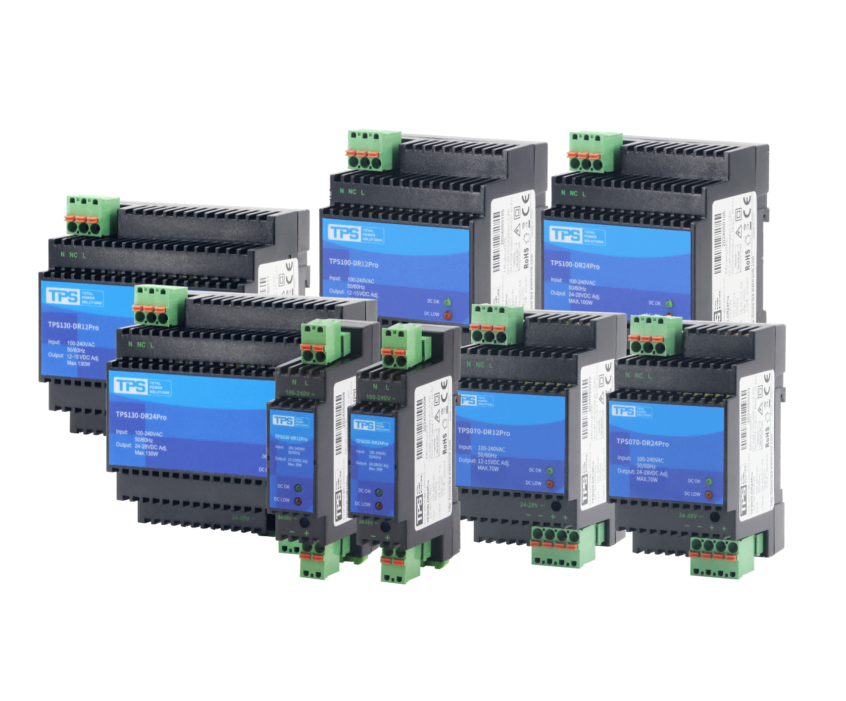
Space inside a control panel is never a luxury. Every added component competes for the same few centimeters of DIN rail, and traditional power supplies often force you to sacrifice functionality or leave awkward gaps. Compact power modules flip that equation. They deliver the same reliable output as bulkier units but pack it into a footprint that respects the tightest layouts. You gain room for extra I/O, better cable routing, or simply cleaner thermal separation—without having to move up to a larger enclosure.
What makes these modules truly useful is not just their physical size, but how they behave under load. Many slim designs still push heat into the surrounding wiring or need derating above 40°C. The newer generation of compact units handles full rated current at higher ambient temperatures, often with active power factor correction and wide-range input. That means you can mount them next to drives or relays without worrying about thermal drift or nuisance tripping. The result is a panel that runs cooler and spends less time in troubleshooting.
For retrofits, the advantage is even clearer. Swapping a legacy power supply for a compact module often frees enough rail space to add a small PLC or a row of terminals—without changing the enclosure. In new builds, it lets you shrink the cabinet footprint from day one, cutting both hardware cost and factory floor space. When every millimeter counts, the right power module stops being just a component and becomes a design strategy.
Efficiency Beyond the Datasheet: Thermal Behavior and Lifetime Impact
Manufacturers quote efficiency at 25°C junction temperature, but real converters rarely stay there. Once a board heats up, conduction losses climb with MOSFET on-resistance, diode forward drops shift, and magnetic core losses creep upward. In a 48V bus converter running at 60°C ambient, the actual efficiency often sits two to three points below the headline figure, not because the part is defective but because the datasheet number is a snapshot, not a field condition.
That gap has consequences for lifetime. Electrolytic capacitors are the usual weak link: every 10°C rise in internal hot-spot temperature roughly halves their service life. Thermal cycling also stresses solder joints and accelerates bond wire fatigue, especially in modules with large die areas. A design that looks comfortable on paper at 95% efficiency may push a capacitor bank past its thermal endurance limit after a few thousand hours of load transients.
The practical fix is to treat thermal resistance as a dynamic parameter. Measuring case temperature under worst-case load, then mapping hot spots with a thermal camera, often reveals a 10–15°C spread across the PCB. Adding a small copper pour, repositioning a sense resistor, or improving airflow through the converter’s narrowest gap can recover more lifetime than swapping to a higher-spec part. Efficiency beyond the datasheet is less about chasing decimals and more about keeping the real hot spots below the thresholds that silently shorten field life.
Built-In Protection That Keeps Automation Running Through Faults
Faults in automated systems are inevitable, but the way a system handles them separates true resilience from fragile setups. Built-in protection goes beyond basic circuit breakers or fuses; it actively monitors every critical path, detects anomalies in milliseconds, and isolates only the affected segment. The rest of the process keeps moving, with no panic stops or cascading failures. This isn't just about surviving a short circuit—it's about preserving throughput even when a sensor fails, a motor stalls, or a communication line drops.
A key part of this protection is redundancy that doesn't just sit idle. Power supplies, communication channels, and control loops cross-check each other continuously. If one leg of a control network goes down, the system instantly reroutes commands through a secondary channel without missing a beat. Diagnostic routines run in the background, logging every fault signature so maintenance crews know exactly what to replace before the next shift. The result is automation that behaves less like a brittle chain and more like a living organism with built-in healing.
For operators, this built-in resilience means fewer alarm floods and less manual override. The system handles transient issues on its own, keeps outputs within spec, and tells you what happened afterward. That shift from reactive troubleshooting to proactive watching changes the whole relationship with the machine. You stop babysitting the line and start managing the process, knowing that a single fault won't bring everything to a grinding halt.
Adding Power Diagnostics Without a Separate Monitoring Network
Power diagnostics have long demanded their own set of sensors, cabling, and network infrastructure, which turns even small installations into a maze of extra hardware. By folding the diagnostic layer directly into the existing control and communication path, the need for that parallel monitoring network disappears. The same wires that carry operational commands also stream back voltage, current, and temperature readings from each load point.
Folding diagnostics into the existing control loop changes how faults are traced. A single dashboard shows both control status and health metrics side by side. Maintenance staff no longer switch between a primary system and a separate diagnostic tool to trace a fault—they see the drop in line voltage, the rise in resistance, or the thermal drift right where the switching action happens. It also removes a common failure source: fewer connectors, fewer isolated segments, and fewer points where a monitoring-only network can go silent without anyone noticing.
When conduit space is tight and budgets are constrained, the absence of a parallel network becomes the strongest selling point. You avoid pulling dedicated diagnostic cables through ducts that are already full, and you skip the cost of duplicate transceivers and gateways. Diagnosis becomes a native feature of the power path rather than an add-on that competes for space and attention.
Sizing and Derating for Mixed PLC, HMI, and I/O Loads
Mixing PLC, HMI, and I/O modules on one power supply creates a sizing problem that simple addition cannot solve. Each device has a different inrush profile, duty cycle, and steady-state draw. A small PLC might pull 8 watts continuously, while an HMI backlight can spike to 20 watts during startup, and a bank of relay outputs may demand 5 watts per point when energized. The right approach is to calculate the worst-case continuous load, then add the peak transient demand separately, rather than just summing nameplate ratings.
Derating needs to account for the physical environment, not just the electrical math. At 50°C ambient, most industrial supplies lose 25–35% of their rated capacity. When the same enclosure holds heat-generating components like relay cards or HMI inverters, internal temperature climbs higher than the room. Airflow restrictions, high altitude, and tightly packed wire ducts all eat into available current. A safer practice is to run the supply at no more than 70–80% of its rated output after ambient correction, leaving headroom for voltage dips and future expansion.
In practice, start by listing every PLC slice, HMI display, and I/O card with its exact current at the nominal voltage. Multiply each by a diversity factor: not all outputs switch at once, and many analog inputs draw negligible power. Add the HMI's peak backlight current during power-up, then apply the temperature derating curve from the supply manufacturer. The final number often surprises designers who were used to a rule-of-thumb 100% margin. For example, a mixed system that totals 10 amps at 24 VDC might require a 15-amp supply once derating and peak inrush are included.
FAQ
Start with the input voltage range and whether it covers your facility's mains fluctuations. Then check the output voltage tolerance, hold-up time, and overload behavior. A wide-range AC/DC input with active power factor correction often saves space and reduces harmonics. Also confirm the unit carries UL 508 or IEC 61010 certification for panel use.
Add up the continuous current requirement of every PLC, sensor, relay, and HMI on the circuit, then add 20 to 30 percent headroom for inrush currents and small future additions. If the panel will operate above 50 degrees Celsius, check the manufacturer's derating curve and consider a larger unit or forced ventilation.
In most industrial applications, yes. Higher efficiency means less heat dissipated inside the enclosure, which reduces thermal stress on all components and can eliminate the need for a cooling fan. Over a five-to-ten-year service life, the energy savings alone often justify the price difference.
Redundant configurations use two or more power supplies connected through diode or MOSFET decoupling modules. If one supply fails or is removed for service, the remaining unit continues to power the load without a break. This is standard practice for safety PLCs, emergency shutdown loops, and continuous process controls.
Many industrial models accept a wide DC input range in addition to standard AC, which makes them suitable for battery-backed control circuits. Check the datasheet for the minimum and maximum DC voltage limits, reverse polarity protection, and whether the output remains stable during battery discharge.
Overvoltage, overcurrent, short-circuit, and overtemperature protection should be built in. Active current limiting and auto-recovery behavior are preferable to latch-off modes, because they allow the system to restart after a temporary fault. Also look for transient suppression to handle inductive loads and noisy switching on the factory floor.
Heat accelerates the aging of electrolytic capacitors, which are often the first components to fail. Operating a unit at 60 degrees Celsius instead of its maximum rated 70 degrees can extend its life significantly. Leave vertical spacing between supplies and ensure natural convection airflow inside the control cabinet.
For general industrial control panels, UL 508 and CSA C22.2 are common for North America, while IEC/EN 62368 or 60950 covers Europe. If the panel is part of a process control system, IEC 61010 may apply. Marine, hazardous area, or railway installations may require additional approvals such as ABS, ATEX/IECEx, or EN 50155.
Conclusion
Industrial control panels rarely enjoy the stable mains voltage promised in datasheets. A DIN rail supply that holds its output through brownouts, sags, and surges matters more than peak efficiency numbers on paper. Look for units with a wide input range and active power factor correction, because real-world line fluctuations can force lesser supplies into nuisance shutdowns. At the same time, control panel space keeps shrinking. Compact power modules that mount side by side without derating clearance gaps let you reclaim valuable rail space, yet the smallest footprint is worthless if heat shortens component life. The best designs pair high efficiency with low internal temperature rise, meaning they run cooler at full load and survive years of continuous duty without electrolytic capacitors drying out prematurely.
Built-in protection separates a robust automation power supply from a generic one. Overcurrent, overvoltage, and short-circuit handling should clamp faults locally instead of cascading through the panel. More advanced units add a diagnostic output or front-panel LED status, so you can spot a failing supply without pulling a separate monitoring network into the project. Finally, sizing is not a single number. Mixed PLC, HMI, and I/O loads do not draw current uniformly; inrush from field devices and momentary CPU spikes call for thoughtful derating. A supply rated at 10 A may only be comfortable at 6 A continuous if the ambient temperature climbs or the panel lacks ventilation. Building in that margin keeps the entire automation system predictable.
Contact Us
Contact Person: Lily
Email: [email protected]
Tel/WhatsApp: +49 (0) 2161 49526-0
Website: https://tps-elektronik.com/en/